
Clamping Force in Injection Molding: Formula & Optimization Tips
2025-03-27 15:25:35
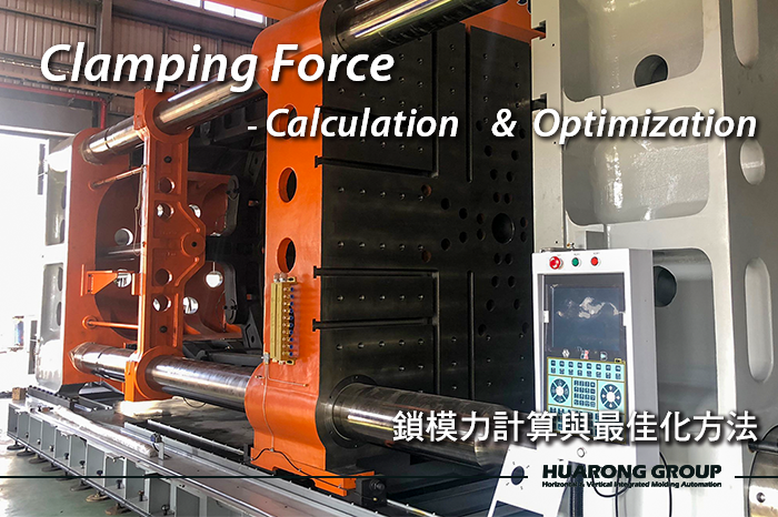
Clamping force in injection molding refers to the machine’s ability to keep the mold securely closed during plastic injection. It is a critical factor for part quality, machine efficiency, and mold longevity. In this comprehensive guide, we explain what clamping force is, how to calculate it using a simple formula, what factors influence it, and how to optimize it in real-world production settings. Whether you are selecting a new injection molding machine or troubleshooting part defects, understanding clamping force is essential.
Clamping force refers to the pressure applied by the injection molding machine's clamping unit to keep the mold halves securely closed during the injection and cooling processes. This force counteracts the internal pressures exerted by the molten plastic as it is injected into the mold cavity, preventing defects such as flash or part deformation. It represents the force required to close the injection mold effectively.
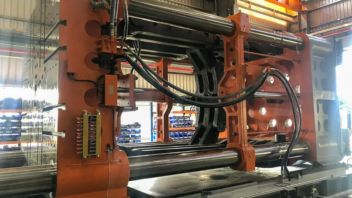
Clamping force is a key performance indicator in injection molding. Without sufficient force, the mold may slightly separate, leading to issues such as flash, short shots, or dimensional inconsistencies. Excessive clamping force, however, can cause premature mold wear or damage. The key factors influencing the required clamping force include:
Further reading: Common Injection Molding Defects: Causes, Types, and Solutions
1. Projected Area of the Part (A)
The projected area of the part is the primary factor in tonnage calculation since the molten plastic exerts pressure perpendicular to the mold's parting surface.
- Larger projected area → Higher mold clamp tonnage required
- Multi-cavity molds significantly increase the projected area, requiring a higher clamping force
Example:
If a product’s dimensions double, its projected area becomes four times larger, leading to a much higher clamping force requirement.
2. Cavity Pressure (P)
Cavity pressure is another critical factor that affects injection molding clamp pressure. It varies depending on the injection molding material, design, and molding conditions.
Typical Cavity Pressures for Different Materials:
| Material | Cavity Pressure (kg/cm²) |
|---|---|
| PP / PE | 250 – 400 |
| PS / ABS | 300 – 500 |
| PC / PA | 400 – 600 |
| GF+PA, GF+PP | 600 – 800 |
3. Injection Conditions
Injection Speed and Injection Pressure influence in-mold pressure. High injection pressure increases cavity pressure, which raises the clamp force vs injection pressure.
- Injection Speed:
- High-speed injection can generate higher in-mold pressure, increasing clamping force requirements.
- When the injection speed is low, the mold pressure is more stable, and the required clamping force is lower.
- Injection Pressure:
- Injection pressure affects the dynamics of melt filling.
- High injection pressure (>150 MPa) may increase the in-mold pressure, necessitating a higher clamping force.
4. Product Design Considerations
Different wall thicknesses and shapes influence the projected area and required force.
- Thick-walled vs. Thin-walled Parts:
- Thick-walled parts require higher injection pressure → higher cavity pressure → higher clamping force.
- Thin-walled parts require a lower clamping force due to their reduced resistance.
- Flat vs. Cylindrical Parts:
- Flat parts (e.g., trays and panels) require a higher clamping force due to larger projected areas.
- Cylindrical parts (e.g., bottles, barrels) generally require lower clamping force.
5. Common Causes of Clamping Force Deviation
Even with precise calculation, clamping force may fluctuate in actual molding conditions due to several real-world variables:
- Mold Wall Temperature Rise: Heat from molten plastic raises mold temperature, leading to thermal expansion and changes in rigidity that affect force distribution.
- Hydraulic Oil Viscosity Fluctuation: In hydraulic systems, oil temperature variations alter viscosity, impacting pressure transmission and clamping consistency.
- Tie Bar Fatigue: Repeated mechanical stress causes tie bars to stretch or weaken, leading to uneven or reduced clamping force.
- Ambient Temperature Variations: Environmental temperature shifts can influence material expansion and mechanical behavior, especially in machines without thermal compensation.
- Frictional Heat in the Toggle System: Long production cycles generate internal heat in toggle mechanisms, affecting their ability to maintain accurate and consistent force.
Summary
| Affecting Factors | Result |
|---|---|
| Projected Area of the Part | The larger the product projection area, the higher the clamping force required. |
| Cavity Pressure | High-pressure materials (such as GF+PA) require greater clamping force. |
| Injection Conditions | High-speed injection and high injection pressure will increase the clamping force requirements. |
| Product Design Considerations | Thick-walled and large-surface products require higher clamping force |
| Common Causes of Clamping Force Deviation | Mold wall temperature rise, hydraulic oil viscosity fluctuation, tie bar fatigue, ambient temperature variations, and frictional heat in the toggle system |
Clamping force is calculated based on the projected area of the part and the cavity pressure using the formula:
Where:
- F = Clamping force (kN or tf)
- A = Projected area of the part (cm²)
- P = Cavity pressure (kg/cm²)
Step-by-Step Calculation Example
Step 1: Calculate Projected Area (A)
Projected Area refers to the total area of a product projected from the mold's parting surface. The calculation method is as follows:
- If the product has a single flat surface, simply calculate the product of its length and width:
- If the product has an irregular shape, the maximum projected area can be measured using CAD software or manually divided into geometric shapes for calculation.
- Multi-cavity molds:
Step 2: Determine Cavity Pressure (P)
In the previous section, “2. Cavity Pressure (P),” we discussed how material properties, injection parameters, product design, and mold structure influence cavity pressure. Therefore, even with the same material, the cavity pressure can vary.
Below is an example based on PP material, with a cavity pressure range of 250–400 kg/cm²:
(1) Product Wall Thickness
| Wall Thickness | Recommended Cavity Pressure (kg/cm²) | Notes |
|---|---|---|
| Thick wall (>3mm) | 250 – 300 | Lower flow resistance allows for low-pressure filling. |
| Standard thickness (1.5–3mm) | 300 – 350 | Applicable to most PP products. |
| Thin wall (<1.5mm) | 350 – 400 | Higher pressure required to avoid short shots and ensure flowability. |
(2) Product Size and Flow Length
| L/T Ratio | Recommended Cavity Pressure (kg/cm²) | Applicable Products |
|---|---|---|
| < 100 | 250 – 300 | Small parts with short flow lengths. |
| 100 – 200 | 300 – 350 | Most PP products with moderate flow lengths. |
| > 200 | 350 – 400 | Long flow paths or thin-walled products. |
(3) Mold and Runner Design
| Mold Characteristics | Impact | Recommended Cavity Pressure |
|---|---|---|
| Cold runner, small gate | Higher resistance | 350 – 400 kg/cm² |
| Cold runner, large gate | Moderate resistance | 300 – 350 kg/cm² |
| Hot runner | Low resistance | 250 – 300 kg/cm² |
(4) Injection Parameters
| Injection Settings | Impact | Recommended Cavity Pressure |
|---|---|---|
| High-speed injection | Requires higher pressure | 350 – 400 kg/cm² |
| Low-speed injection | Lower filling pressure sufficient | 250 – 300 kg/cm² |
(5) PP Additives and Grades
| PP Grade | Characteristics | Recommended Cavity Pressure |
|---|---|---|
| General-purpose PP | Standard flowability | 300 – 350 kg/cm² |
| High-flow PP (MI ≥ 20) | Easier flow, lower resistance | 250 – 300 kg/cm² |
| Glass fiber reinforced PP (GF+PP) | High resistance | 400 – 500 kg/cm² |
Step 3: Calculate Clamping Force (F)
Multiply A and P to get the required mold clamp tonnage.
Further reading: What are Fundamentals of Injection Molding? 3 Keys to Plastic Injection Plant
When selecting an injection molding machine for a plastic product (e.g., a 250ml ice cream tub), and complete design data is not yet available, how can we quickly estimate the required clamping force on the spot?
Example of Quick Estimation
Related Product Video: HR-150IML 250cc Cup
Related Product for the machine: General injection molding machine – HRN series
Related Product for in-mold labeling: IML series
For On-Site Customer Interaction:
| Question | Customer Response |
|---|---|
| What is the cup capacity? | 250ml |
| What is the cup’s diameter and height? | 8.5 cm / 9 cm |
| How many cavities in the mold? | 4 cavities |
| What material is being used? | PP |
| Estimated cycle time? | High-speed mass production (implies thin wall) |
Then you can quickly estimate in your head (or use your phone calculator):
(1) Projected Area
= π × (8.5 / 2)² × 4 ≈ 227 cm²
(2) Cavity Pressure
= 350–400 kg/cm² → 227 × 400 = approx. 91 tf
(3) Add Safety Margin of 20-30% for the actual machine selection
= 120 tf or more → Recommend using 150 tf
- Ensure accurate measurement of the projected area, especially with multi-cavity molds.
- Select a suitable cavity pressure based on the type of plastic material used.
- Select a clamping force slightly higher than the calculated value to prevent mold opening during injection.
- Avoid excessively high clamping force to extend mold life and reduce energy consumption.

- Select a clamping force a 20–30% safety margin to the calculated requirement to reduce machine load during long-term production.
- Reduce injection speed or cavity pressure to lower the required clamping force.
- Utilize optimized mold designs (e.g., reducing projected area and streamlining the runner system) to minimize clamping force requirements.
- Consider the right injection molding machine types—for larger molds, a two-platen injection molding machine may be more suitable for larger molds.
To ensure consistent part quality, energy efficiency, and extended machine life, consider the following optimization strategies:
- Use the Minimum Required Clamping Force: Avoid overusing the machine’s maximum clamping capacity. Apply only the necessary force based on actual calculations to reduce energy consumption, mold wear, and machine fatigue.
- Improve Mold Rigidity: Strengthen the mold base and steel frame to resist flexing under high pressure. A more rigid mold allows for even force distribution, helping prevent parting-line flash and dimensional defects.
- Upgrade Clamping Mechanism: Advanced toggle designs with symmetric or external balanced links help deliver uniform clamping force across the entire mold surface. This improves shot consistency and part precision.
- Real-Time Monitoring Systems: Install strain gauges or tie bar sensors to monitor real-time clamping force. Many modern machines offer automated force correction capabilities, dynamically adjusting clamping force during each cycle.
- Scheduled Maintenance: Perform regular maintenance on the toggle mechanism, hydraulic unit, lubrication system, and tie bars. Preventive inspections ensure consistent performance and reduce the risk of force deviation over time.
What happens if the clamping force is too low or too high?
Choosing incorrect clamping force can lead to costly consequences:
- Too low → Mold opens during injection → Flash, part defects
- Too high → Tool wear, excess energy use, no added value
Proper tonnage calculation supports better injection machine tonnage selection, ensuring longevity and reliability.
How much safety margin should I consider?
Add 20-30% to the calculated clamping force.
Can clamping force be adjusted on the machine?
Yes, within the machine’s rated maximum clamping capacity.
Is bigger clamping force always better?
No. Oversized clamping force increases cost and wear without improving part quality.
Clamping force is vital to injection molding, ensuring the mold stays securely closed against high pressure. By understanding what clamping force is, how to calculate it using the clamping force formula, and how to measure it, injection molding businesses can optimize production efficiency, minimize defects, and extend the lifespan of their equipment.
- Group Name: Huarong Group
- Brand: Huarong, Yuhdak, Nanrong
- Service Offerings: Injection Molding Machine, Vertical Injection Molding Machine, Injection Molding Automation
- Tel: +886-6-7956777
- Address: No.21-6, Zhongzhou, Chin An Vil., Xigang Dist., Tainan City 72351, Taiwan


The Huarong Marketing Team is dedicated to translating Huarong’s deep manufacturing expertise into clear, actionable insights for our global audience. By collaborating closely with our R&D and engineering departments, we ensure that every update on injection molding machine technology and industry trends is presented with accuracy and practical value, reinforcing Huarong’s position as a premier injection molding machine manufacturer.
- Expert Insights: Regular updates on injection molding machine optimization and efficiency.
- Proven Reliability: 40+ years as a leading injection molding machine manufacturer in Taiwan.
- Global Reach: Tailored manufacturing solutions for automotive, medical, and packaging sectors.