Injection Molding Cycle Time: The Key to Faster and Smarter Manufacturing
2025-04-25 11:43:53
Injection molding cycle time is one of the most crucial metrics in plastic manufacturing. It directly affects your production efficiency, the cost per part, and even the longevity of your equipment. In this article, we will delve into the meaning of cycle time, the factors that influence it, and proven strategies to optimize it for your molding operations.
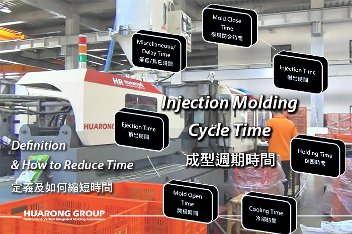
The injection molding cycle time refers to the total time taken to complete one full production cycle of a molded part—from mold closing to part ejection and mold opening again.
- Mold Close Time: This is the time during which the mold closes and locks under pressure.
- Injection Time: Molten plastic is injected into the mold cavity through the nozzle. Duration depends on shot size, injection speed, and mold flow resistance.
- Holding Time: This stage maintains mold pressure to compensate for shrinkage as the plastic cools, ensuring full cavity fill and preventing defects such as sink marks and voids.
- Cooling Time: The most time-consuming phase is when molten plastic solidifies in the mold.
- Mold Open Time: After cooling, the mold opens to eject the part.
- Ejection Time: This refers to the time required to eject the molded part using ejector pins or a robotic arm. If the part sticks or if multiple strokes are needed, this time increases
- Delay Time / Miscellaneous Time: This covers any other programmed or unplanned time between steps, such as:
- Safety interlocks and signal checks
- Robot movement or conveyor belt delays
- Manual interventions (if applicable)
- Machine response lag due to hydraulic delay or control system latency
The shorter your cycle time, the more parts you produce per hour—this directly impacts:
- Production Capacity
- Cost per Part
- Order Fulfillment Speed
- Machine Utilization Rate
Example:
- 30s cycle = 120 shots/hour
- 25s cycle = 144 shots/hour ➜ +20% Efficiency
Even a 2-second reduction in a high-volume operation can lead to substantial output increases.
This question is among the most commonly asked in injection molding. Reducing cycle time cannot depend solely on machine speed. It is crucial to simultaneously integrate "mold", "machine", "finished product design", "process control", and "automation system", addressing each aspect simultaneously. Here are some suggested directions for reference:
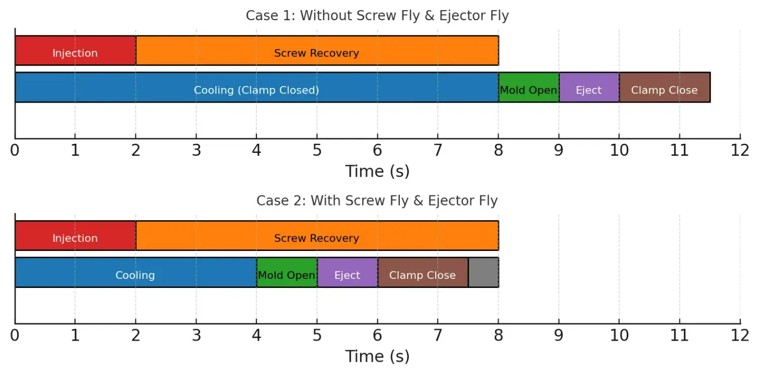
Also known as: Simultaneous Plasticizing and Mold Opening
This technique enables the machine to plasticize the next shot while the mold is opening, rather than waiting until the mold is fully open and the part is ejected.
Benefits:
- Overlap the cooling and material preparation stages
- Cuts idle time and improves cycle overlap efficiency
- Reduces total cycle time by up to 10–20%
- Works best with direct-drive material storage systems (like Huarong’s), which also save up to 26% energy
Best suited for:
- Large parts with long cooling times
- High-volume production
- Machines with independently controlled plasticizing systems
Also known as: Simultaneous Ejection and Mold Opening
Instead of waiting for the mold to open fully, the ejection mechanism is triggered as the mold starts to open, with proper safety margins in place.
Benefits:
- Reduces mechanical lag by overlapping steps
- Accelerates the ejection process
- Ideal for simple shapes and robust designs
Best suited for:
- Shallow molded parts
- Standardized mass production
- Parts with non-delicate surfaces
This configuration decouples injection and plasticizing processes using separate units—a plunger for injection and a screw for plasticizing.
Benefits:
- Simultaneous operation reduces downtime
- Enhances precision and control over material properties
- Ideal for high-precision, multi-material, or microcellular foam molding
Best suited for:
- Precision parts
- Multi-color or multi-material molding
- Sensitive materials (e.g., supercritical fluid applications)
| Configuration | Key Advantage | Cycle Time Impact | Complexity | Best For |
|---|---|---|---|---|
| Screw Fly | Overlaps plasticizing with mold open | High | Low | High-speed, large-shot machines |
| Ejector Fly | Overlaps ejection with mold opening | Medium | Low | Fast-cycling small parts |
| Injection/Plasticizing Sep. | Simultaneous plasticizing and injection | Very High | High | High-precision, thin-wall, PET |
- Segmented Injection Speeds: Prevents defects such as flash or short shots.
- Holding Time Tuning: Based on shrinkage and wall thickness.
- Mold Open Speed Control: Fast open with slow stop for accuracy and speed.
- Motion Overlap: Combine mold open and ejector operations.
- Ensure even cooling in key areas.
- Use temperature controllers for heat stability.
- Add dual-loop or thermal-balanced water channels.
- Adopting Microcellular Foam Injection Molding Technology
This advanced foaming method introduces supercritical fluid (such as N₂ or CO₂) into the polymer melt to form a fine and uniform cellular structure. It brings the following benefits:- Shortens Cooling Time:
- Reduces Part Weight and Injection Pressure:
- Improves Dimensional Stability and Warpage Resistance:
- Foamed materials have lower density, which enhances their thermal conductivity.
- Eliminates the need for full-thickness cooling—allowing earlier demolding.
- Typically reduces cooling time by 20–30%.
- Ideal for structural components or non-density-critical shells (e.g., logistics containers, tool housings).
- Lowers required injection pressure and clamping force, enabling quicker mold movements.
- Micro-bubbles balance internal stress and enhance part accuracy.
Further reading: Microcellular Foam Injection Molding: Achieving Maximum Weight Reduction and Dimensional Stability
- Synchronized Robotic Arm Part Removal: Coordinates with mold opening to reduce wait time and improve safety and consistency.
- Integrated Gate Cutting, Packaging, and Assembly: Post-mold processes, such as trimming and packing, can now occur in parallel with mold operations, reducing the overall production cycle.
- Dual-Slide or Rotary Table Systems (in Vertical Injection Machines): A/B station operations enable one side to eject while the other side injects—minimizing downtime through continuous workflow.
- In-Mold Labeling (IML): Applies labels directly during the injection process, eliminating the need for secondary operations.
- Smart Factory Management System
- Continuously track parameters such as cycle time, injection pressure, holding pressure, mold temperature, and mechanical actuation timing.
- Detect cycle anomalies and send instant alerts for early intervention and traceability.
- Remote Diagnostics Support: Enables off-site troubleshooting during machine faults or molding defects, effectively reducing machine downtime and improving operational efficiency.
Cycle Time refers to the total time required to complete one full injection molding process—from the start of mold closing to the start of the next identical cycle. It includes
Cycle Time is typically measured in seconds. The general formula is:
In practice, some customers use the cycle summary on the machine’s interface or analyze it via the controller or cycle monitoring system.
Example breakdown:
- Mold Close: 1.5 s
- Injection: 2.0 s
- Holding: 3.0 s
- Cooling: 15.0 s
- Mold Open: 1.2 s
- Ejection: 1.3 s
- Total Cycle Time = 24 seconds
There is no fixed “standard” cycle time—it varies greatly depending on several factors:
Key Influencing Factors
- Part size and wall thickness – thicker parts require longer cooling.
- Number of cavities – multi-cavity molds may extend ejection or mold open time.
- Plastic material properties – e.g., PA and PC cool more slowly than PP or PE.
- Mold cooling efficiency – well-designed cooling circuits reduce cycle time.
- Use of automation – robots, quick-change molds, and advanced controllers enhances efficiency.
| Application Type | Common Cycle Time Range |
|---|---|
| Small parts (caps, connectors) | 10–20 seconds |
| General appliances, auto parts | 25–45 seconds |
| Thick-walled, large products | 60–90 seconds |
In practice, when excluding cooling time and describing only the mechanical movements, we refer to the Dry Cycle Time.
It indicates the machine’s baseline mechanical capability.
Dry Cycle Time is the mechanical cycle time for:
This test excludes the mold, material, injection, and cooling steps, and reflects the minimum motion time.
- Larger machines have longer dry cycles due to:
- Smaller machines have faster dry cycles due to shorter motion travel and lighter mold plates.
- Longer stroke distances
- Heavier platens
Cycle time optimization in injection molding isn’t about tweaking one parameter—it’s a comprehensive, system-level integration.
As discussed throughout this article, true cycle time efficiency involves:
- Motion synchronization and speed segmentation
- Microcellular foam molding and direct drive plasticizing systems
- Efficient cooling channel designs
- In-mold automation
- Smart system data monitoring
Each element, when fine-tuned, contributes to tangible productivity gains and can make a meaningful difference in factory throughput and competitiveness.
- 10–30% increase in hourly output, improving delivery flexibility and market competitiveness
- Lower unit cost by reducing energy, labor, and material waste
- Smoother production rhythm, supporting better quality control and scheduling
- Supports ESG goals through energy-efficient upgrades and sustainable manufacturing technologies
Are you planning to optimize your injection molding performance, integrate automation, or establish a smart factory setup?
With over 40 years of injection molding expertise, Huarong provides professional equipment consulting and planning services to help you transition to high-efficiency, low-energy, intelligent manufacturing.
- Group Name: Huarong Group
- Brand: Huarong, Yuhdak, Nanrong
- Service Offerings: Injection Molding Machine, Vertical Injection Molding Machine, Injection Molding Automation
- Tel: +886-6-7956777
- Address: No.21-6, Zhongzhou, Chin An Vil., Xigang Dist.., Tainan City 72351, Taiwan