Injection Molding Machine Manual at Huarong Machine
2024-08-08 13:47:14
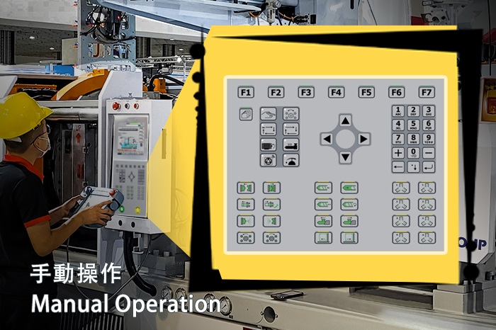
Many new operators of Huarong machines struggle with unfamiliar controllers. This comprehensive guide covers button functions and is designed for your ease and comfort.
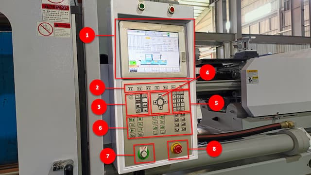
The injection molding machine plc controllers are designed for user efficiency. They are segmented into eight distinct parts, each with specialized functions. Familiarizing yourself with these features is the first step toward efficient injection molding machine operation.
Instruction Manual
- LCD and Touch Screen: Centralized display for monitoring machine operations.
- F1 ~ F7 Buttons: These buttons allow you to change the screen page and convert it to the selected function screen.
- Mode Selection, Pump, and Heater Buttons: These are control buttons for switching operational modes and managing pump and heater functions.
- Cursor Movement Buttons: Navigate through different settings with these directional keys.
- Number Buttons: Input precise numerical values for various parameters or enter English.
- Action Buttons: Use these buttons to execute specific tasks, such as opening and closing molds, moving injection units, and more.
- Power Up Button: Initialize the machine's power for operation.
- Emergency Button: Instantly halt operations in an emergency, ensuring safety.
The following section will detail the above mode selection, pump, heater, and action buttons and introduce how to use each function while manually operating the injection machine.
Mode Selection, Pump, and Heater Button Operations
These buttons are crucial for setting the machine’s operational mode and controlling essential functions like the pump and heater. Here’s a detailed breakdown of their functionalities:
| Icon | Meaning | Function |
|---|---|---|
 |
[MANUAL] | Switch mode from [FULL AUTO] to [MANUAL] for hands-on control. When pressed, the LED will be ON. |
 |
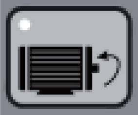
[DIE HEIGHT] | Use this button when changing or installing molds. This enables you to set the zero point for new molds and move forward and backward in slow motion to prevent mold damage. When the button is pressed, the LED light will light up. |
 |
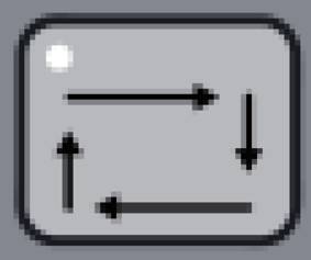
[SEMI AUTO] | In this mode, the machine completes each cycle automatically, but the operator must open and close the safety door to start the next cycle. When the button is pressed, the LED light will light up. |
 |
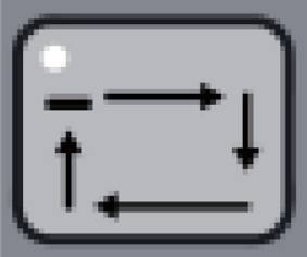
[FULL AUTO] | Enables the machine to run continuously without manual intervention. When the button is pressed, the LED light will light up. |
|
[PUMP] | Activate or stop the pump when in [MANUAL] mode. Note that this function is not available in [FULL AUTO] mode. When the button is pressed, the LED light will light up. |

|
[HEATER] | Activate or stop the heater when in [MANUAL] mode. Note that this function is not available in [FULL AUTO] mode. When the button is pressed, the LED light will light up. |
 |
[ALARM ACK] (Acknowledge) |
When an alarm occurs, press this button to stop it. Note that if the cause of the alarm is not eliminated within a certain time (you can set this yourself or according to the default time), the alarm will occur again. |
 |
[LUBRICATE] | Activate lubrication when in [MANUAL] mode to ensure the smooth operation of machine components. |

|
[INDEX] | This menu button returns you to the main screen, updating the content related to the F1~F7 buttons. |
Action Button Functions and Procedures
The Action buttons give you direct control over various machine functions, making them critical for manual operation.
| Icon | Meaning | Function |
|---|---|---|
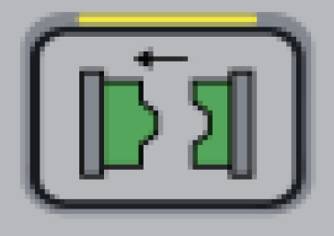 |
[MOLD OPEN] | While in [MANUAL] mode, press the button to open the mold based on the set parameters. The operation automatically halts when the button is released. |
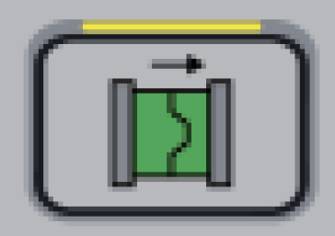 |
[MOLD CLOSE] | While in [MANUAL] mode, press the button to close the mold according to preset parameters, ensuring all components, such as cores and injection molding robots are in place before operation. |
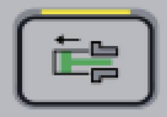 |
[EJECTOR BWD.] (Backward) |
While in [MANUAL] mode, press the button to retract the ejector. Ejector movement will stop once the button is released, or the back limit is reached. |
 |
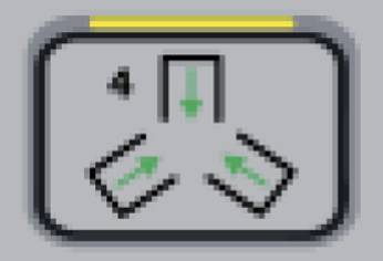
[EJECTOR FWD.] (Forward) |
When the mold is fully opened, and the cores have retracted, press it in [MANUAL] mode to initiate continuous ejector movement based on the frequency. |
 |
[AIR BLOW MOVE] | While in [MANUAL] mode, press the button to activate the air blast installed on the moving platen. The blast time is preset at any position of the mold open stroke. |
 |
[AIR BLOW FIXED] | While in [MANUAL] mode, press the button to activate the air blast installed on the fixed platen. As per the set timing, you can activate the air blast platen at any position during mold opening and closing. |
 |
[DIE HEIGHT BWD.] (Backward) |
When the LED of [DIE HEIGHT] button is ON in [MANUAL] mode, press the button to adjust the mold's height backward. |
 |
[DIE HEIGHT FWD.] (Forward) |
When the LED of [DIE HEIGHT] button is ON in [MANUAL] mode, press the button to adjust the mold's height forward. |
 |
[INJECTION] | When the LED of [PUMP] and [HEATER] button are ON and machine's barrel temperature and cold
start
time* reach the preset value in [MANUAL] mode, press the button to initiate the injection
process.
During the process, the pressure and speed will adjust in stages according to the set
values,
transitioning into the final hold pressure stage. Once you release the button, the injection
will
stop immediately. *Cold Start Time: After the temperature reaches the set value, the real temperature in the barrel will not get the set temperature immediately, so a time is set to start operating at a certain time. |
 |
[SUCK BACK] | The [SUCK BACK] starting conditions are the same as the [INJECTION]. Press the button for the retreat action when the back position is before the end of retraction. Once you release the button, the movement will stop immediately. |
 |
[PURGE] | The [PURGE] starting conditions are the same as the [INJECTION]. It cleans the remaining injection molding material in the barrel by activating the purge process according to settings in [MANUAL] mode. |
 |
[SCREW ROTATE] | The [SCREW ROTATE] starting conditions are the same as the [INJECTION]. It initiates screw rotation for material charging. This button will remain pressed until the material storage is completed. Press it again to stop the action midway. |
 |
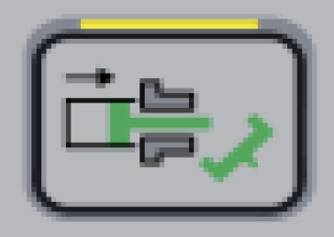
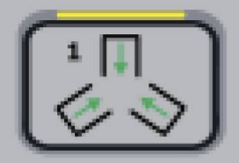
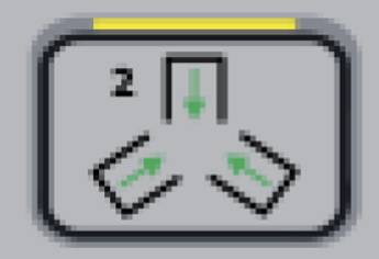
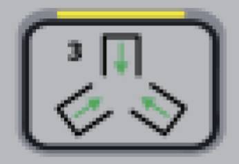
[INJ. UNIT FWD.] (Injection Unit Forward) |
While in [MANUAL] mode, press the button to move the injection unit forward. When the seat comes into contact with the final position of the seat, it will switch to a slow forward speed to prevent the collision between the nozzle and the mold to protect the mold platen. |
 |
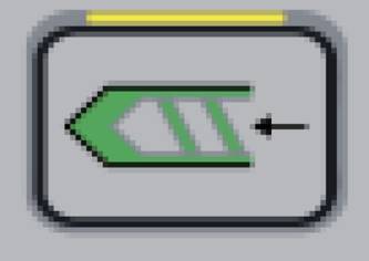
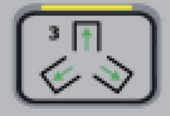
[INJ. UNIT BWD.] (Injection Unit Backward) |
While in [MANUAL] mode, press the button to retract the injection unit. When the seat comes into contact with the final position of the seat, it will not stop, which is convenient for injection molding maintenance and cleaning. |
 |
[AIR DOOR OPEN] | While in [MANUAL] mode, press the button to open the machine’s safety door next to the operator if the machine is equipped with an automatic door-closing function. |
 |
[AIR DOOR CLOSE] | While in [MANUAL] mode, press the button to close the machine’s safety door next to the operator if the machine is equipped with an automatic door-opening function. |
 |
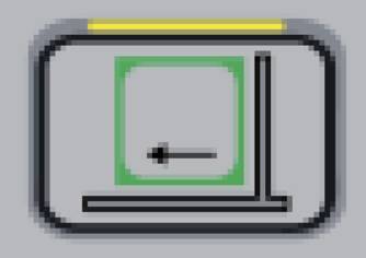
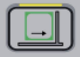
[CORE 1 OUT] | If the machine is equipped, press the button to control core 1 out movement while in [MANUAL] mode. |
 |
[CORE 1 IN] | If the machine is equipped, press the button to control core 1 in movement while in [MANUAL] mode. |
 |
[CORE 2 OUT] | If the machine is equipped, press the button to control core 2 out movement while in [MANUAL] mode. |
 |
[CORE 2 IN] | If the machine is equipped, press the button to control core 2 in movement while in [MANUAL] mode. |
 |
[CORE 3 OUT] | If the machine is equipped, press the button to control core 3 out movement while in [MANUAL] mode. |
 |
[CORE 3 IN] | If the machine is equipped, press the button to control core 3 in movement while in [MANUAL] mode. |
 |
[CORE 4 OUT] | If the machine is equipped, press the button to control core 4 out movement while in [MANUAL] mode. |
 |
[CORE 4 IN] | If the machine is equipped, press the button to control core 4 in movement while in [MANUAL] mode. |
The injection molding controller is a critical component that ensures the precise operation of your injection molding machine. However, like any sophisticated technology, controllers can occasionally encounter issues that disrupt production. Here are some common problems associated with injection molding controllers and their solutions:
Controller Screen Freezes or Becomes Unresponsive
Issue: The controller screen becomes unresponsive or freezes, preventing operators from adjusting or monitoring the machine’s status.
Solution: First, check for any visible signs of damage or loose connections in the control panel. Restart the controller by powering it off and on again. If the issue persists, perform a factory reset according to the machine’s manual. Ensure that the controller software is up-to-date, and consider reinstalling or upgrading the software if necessary. If the problem continues, contact technical support for further assistance.
Incorrect Parameter Settings
Issue: The machine does not perform as expected due to incorrect parameter settings, leading to defects in molded parts or inconsistent production.
Solution: Review the controller’s parameter settings to ensure they align with the specifications for the current molding job. Verify that temperature, pressure, speed, and cycle time settings are correct. If unsure about the correct settings, consult the machine’s operation manual or contact technical support for guidance.
Error Codes Displayed on Controller
Issue: The controller displays error codes or alarms that interrupt machine operation.
Solution: Refer to the machine’s manual or controller documentation to understand the meaning of the error codes. Many controllers have a built-in diagnostic tool that provides detailed information about the issue. Address the underlying cause of the error, whether it’s a mechanical fault, electrical issue, or sensor malfunction. Clear the error codes after resolving the problem and perform a test run to ensure regular operation.
Inaccurate Temperature Readings
Issue: The controller shows incorrect temperature readings, affecting material viscosity and product quality.
Solution: Inspect the thermocouples and temperature sensors for any signs of damage or misalignment. Replace faulty sensors or recalibrate them as necessary. Ensure that the temperature settings on the controller match the requirements for the material being used. It’s also essential to check for software bugs or glitches that might cause incorrect readings and update the controller firmware if needed.
Communication Errors Between Controller and Machine Components
Issue: The controller fails to communicate appropriately with other machine components, such as the hydraulic system or injection unit, leading to operational delays or failures.
Solution: Check all cables and connectors between the controller and machine components for wear, damage, or disconnection signs. Tighten any loose connections and replace damaged cables. Verify that all communication settings in the controller are configured correctly. If the issue remains unresolved, reset the controller’s communication settings and perform a full system reboot.
Controller Overheating
Issue: The controller becomes excessively hot during operation, potentially leading to component failure or reduced performance.
Solution: Ensure the controller is installed in a well-ventilated area with adequate cooling. Clean any dust or debris from the controller’s vents and cooling fans. Check the ambient temperature of the machine environment to ensure it’s within the recommended operating range. If overheating persists, consider installing additional cooling systems or upgrading the controller’s internal cooling components.
Understanding the manual operation of Huarong machines to maximize their performance and ensure operational safety. Following this detailed guide, operators can gain precise control over their machines, leading to efficient and optimized production processes.
If you need further assistance or have any questions, please contact Huarong. We are an experienced injection molding machine manufacturer dedicated to providing expert guidance and support to help you achieve your injection molding needs.
- Group Name: Huarong Group
- Brand: Huarong, Yuhdak, Nanrong
- Service Offerings: Injection Molding Machine, Vertical Injection Molding Machine, Injection Molding Automation
- Tel: +886-6-7956777
- Address: No.21-6, Zhongzhou, Chin An Vil., Xigang Dist., Tainan City 72351, Taiwan
- Official Website: https://www.huarong.com.tw/

Previous news: How Our Vertical Injection Machines Produce High-Quality Tubes for CPAP | Success Story
Next news: Celebrating Innovation and Excellence: Huarong at TaipeiPlas 2024